


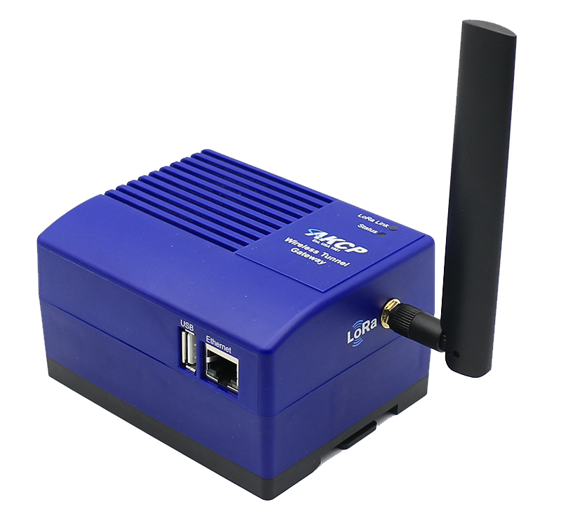
AKCP Wireless Tunnel Gateway (WTG)
Customizable and expandable Wireless Tunnel Sensor Gateway
 Properties
 Description
 Further Information
 Similar products
 Print this page
 Request Price
 show my notes
 PDF
PDF
 Properties
 Description
 Further Information
 PDF
PDF
- Basic Expansion Bus (BEB)
- Cellular Modem
- Modbus
- GPS
- WiFi
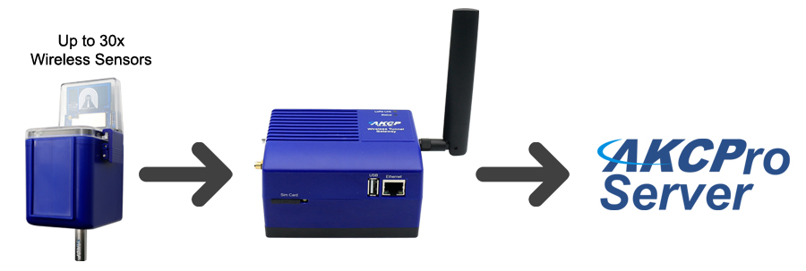
The WTG collects data from up to 30 AKCP Wireless Tunnel Sensors. View data via the embedded Web UI or consolidate data from multiple gateways on AKCPro Server
Custom Options
WiFi:
If the WTG is placed in an area you dont have accessible Ethernet cable for network connection, use the WiFi option to connect with your IP network. WiFi can also function as a hotspot for direct access without a wired or wireless network.
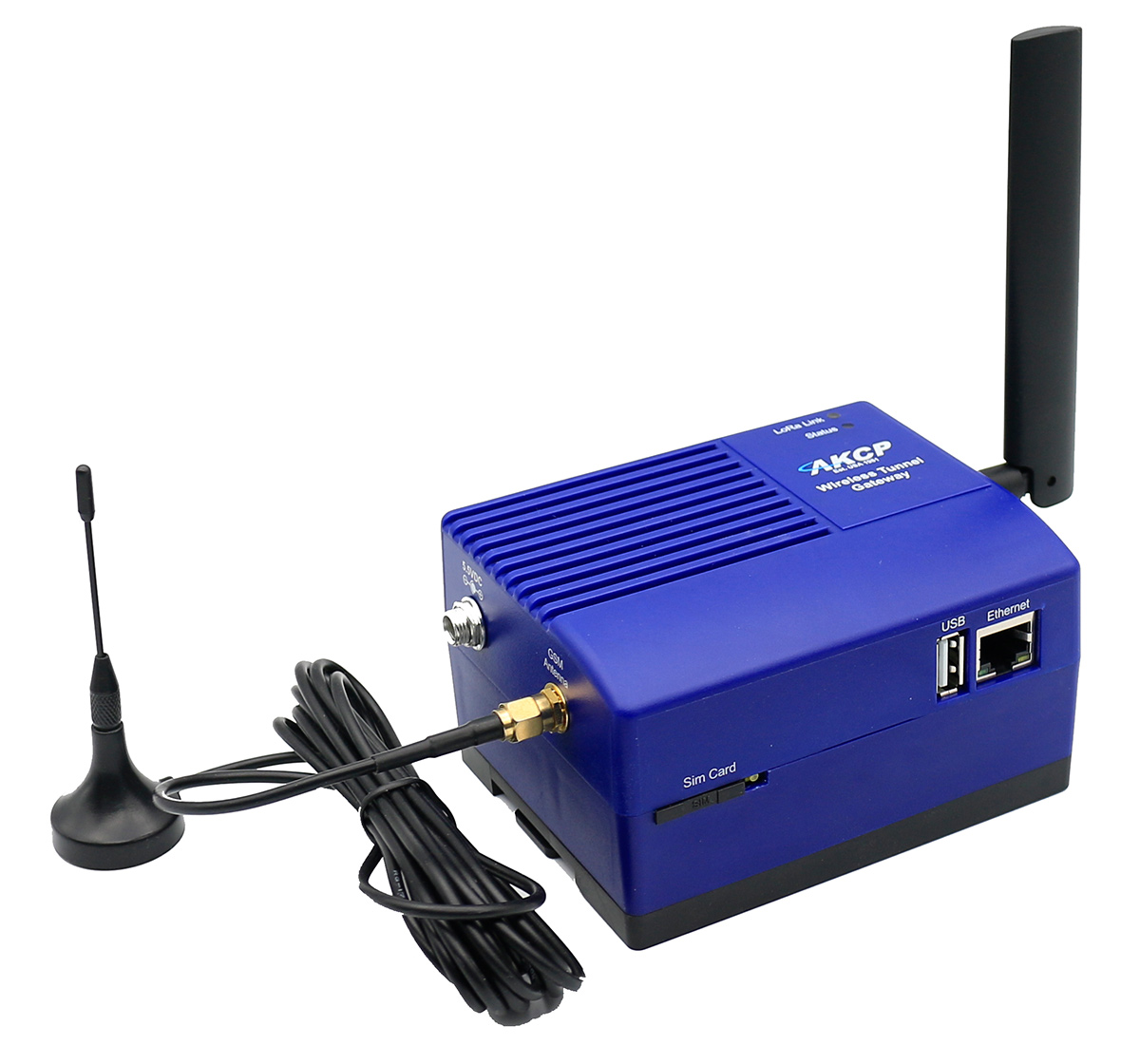
Cellular:
For sites that have no internet connection avaialble, the cellular data modem will transmit all your sensor data over the cellular network. In standalone installations, the cellular modem can also be used for sending SMS alerts. With the internal batteries the WTG will remained powered long enough to alert of power outages via SMS.
GPS:
Geolocate your WTG and monitoring locations on AKCPro Server world map. Geofence the device and know when it has moved out of a defined area.
Modbus:
RS485: RS485: Connect your WTG to 3rd party Modbus devices for monitoring generators and other industrial equipment.
Basic Expansion Bus:
The BEB port allows you to add SPX+ style BEB units for additional dry contact inputs, or wired sensors.
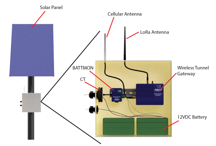
Remonte Sites
When utilized at remote sites the Wireless Tunnel Gateway can be installed with a solar panel under battery power and collect data from sensors up to 1km radius. Communicate over the cellular network with multiple sites monitored from AKCPro Server centralized monitoring software.
Specification
- Status Indication
- EU868 : 863~868Mhz Max TX Power +14dBm Duty Cycle 1%
- US915: 903~915Mhz Max TX Power +17dBm
- AS923 : 920~925Mhz Max TX Power +14dBm Duty Cycle 1%
- KR920 (Korea) : 922~923Mhz Max TX Power +14dBm Duty Cycle 1%
- IL917 (Israel) : 915~917Mhz Max TX Power +14dBm Duty Cycle 1%
- up to 30 Wireless device connected
- up to 32 Wireless sensors can be graphed
- Total of up to 150 sensors can be online (Wireless and Virtual)
LED indication for power
LED for Radio connectivity
LED for Status
Components
Manufactured using highly integrated, low power surface mount technology to ensure long term reliability.
Operating Environment
Temperature : Min. -15° C Max.50° C
Humidity: Min. 20% Max. 80% (Non-Condensing)
MTBF
1,400,000 Hours based on field experience with sensorProbe units.
Connectivity
Ethernet 10/100 Mbps
2.4GHz IEEE 802.11 b/g/n wireless LAN
Optional Integrated 4G cellular modem with external antenna
Optional GPS with external antenna (requires 4G modem)
Inputs
1x USB for LoRa devices adding/software upgrade
1x 10/100 Ethernet Port
Optional Basic Expansion Bus (BEB) Port
Optional Modbus RS485
LoRa (R) Radio Regional plans
Certification
FCC Part 15C, CE EN300220-2
Software features
Power
External 5.5V 3A Power Adapter
Power Adapter Input Voltage and Current ratings : 100V~240V 0.22A
Optional internal UPS with 4x AA Batteries (non-rechargeable)
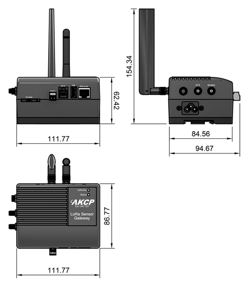
Dimension
111 (W) x 62 (H) x 87 (D)
Mounting
Desktop, wall mount, DIN rail, Magnetic
* Optional feature on custom units
 Datasheet") Customers who viewed this item also viewed
Customers who viewed this item also viewed